This is the first article on how I built my new band saw. I’ll show you how to cut and machine the parts that will support the entire structure of the band saw, as well as the system that allows us to tilt the upper wheel and tense the blade. Here you’ll find the band saw plans:
DIY Band Saw Plans
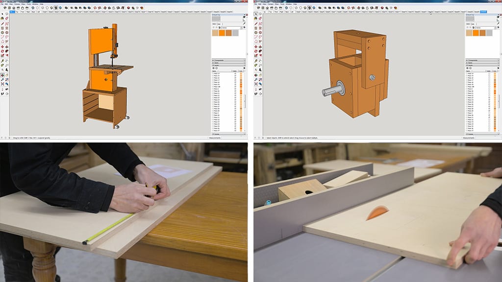
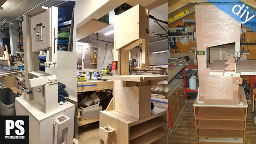
This is the SketchUp 3D model I’ve been working on over the last few weeks. It’s completely made of plywood to make the assembly easier. Once the plywood parts have been cut to size, we’ll basically only have to put them together following the plans.
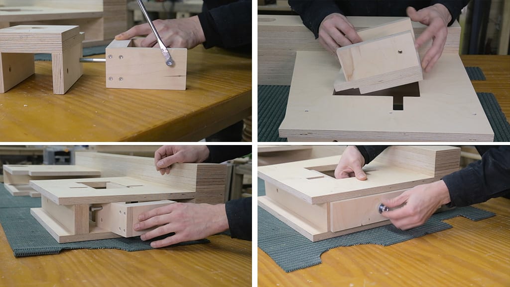
I’m going to use birch plywood, although we could also use lighter plywood or MDF. At any rate, it’s best to use hard plywood for load-bearing pieces, such as the upper wheel’s lifting system (second photo).
I’ll start by machining these two parts(third photo). They’re the biggest of the bunch and provide the structure for the saw. After cutting them to size, I mark all their rebates according to the plans.
I’ll remove the riving knife from my table saw for a moment in order to make the inner rebates. Doing so will allow us to cut the pieces evenly.

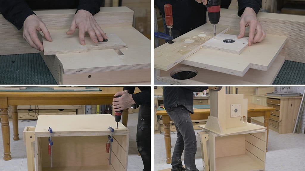
I finish the job with a jigsaw. These are the rebates for the screws that will act as rotation axes in the upper wheel’s lifting system(first photo). Now I drill the holes to insert the lower wheel’s calibrated rod(second photo).
I machine these holes with the router, one for the dust collection pipe and one for the motor. In one of the parts I only need a hole for dust collection(third photo).
This screw will allow us to rotate the table and lock it in place. I’ll use this kind of screw so that it won’t turn when operating the knob. Then I drill a hole the rear piece of plywood for a threaded insert that will allow us to tilt the upper wheel.

Now I can glue both pieces and the pieces inbetween together. I’ll sprinkle salt on all the surfaces so that the parts won’t move when tightening the clamps. I’ll also glue another parts that will act as a buffer and reinforce the structure right under the upper wheel.
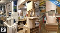
While I’m waiting for the glue to dry, I machine the part upon which the saw’s guide post will slide. Then, after cutting it at the necessary angle, I can put everything in place(second photo).
I’ll also screw in the buffer for the lower parts of the band saw(third photo). Now is good time to make a rebate for the emergency switch, and then I can finish gluing all the reinforcing buffers together like before(fourth photo). While I’m at it, I can also sand and varnish all the parts, especially the edges.

This is the upper wheel’s lifting and tilting system. After cutting all the parts, I mark and machine a hole for the wheel’s calibrated rod with a bit whose diameter is 10mm bigger than the rod’s. I’ll attach this metal plate to the rear where the screw that regulates the tilt will rotate, this way I won’t damage the board(second photo).
I drill holes for the screws that will act as rotation axes, and screw them together. I attach this other part that will allow us to separate the upper bearings a little bit more(third photo). Now I machine the other part of the lifting system.
I drill the upper piece to insert the screw that will allow me to lift the entire set, and I screw them together(fourth photo).
I’ve made some rebates on the heads of these screws allowing easier removal after they’ve been put in place. Mounting the lifting system on the band saw is quite easy. First I put the biggest part from the front, and the other part from the top, having put in the screws/axes. We line up the holes and insert the screws.
I’m going to build a cover for the band saw top by gluing these two parts together. I drill a hole here so that I can lift the upper wheel. By tensing the blade this part will bend, and will act as a spring, preventing the saw from vibrating(fourth photo).

I mark the position of the upper frontal bearing. I’ll use this adjustable bit for this task. First I tried it on another piece of plywood. The hole has to be tight so that the bearing is firmly attached to the board. Using a cheap bit and this drill makes this difficult, but little by little I manage to drill the hole.
Then I insert the bearing using a metal plate. Since the central axis of the bearing is a few tenths of a millimeter smaller than the outer ring, I won’t damage it. I do this carefully, little by little, trying to make it level with the plywood(second photo).
Finally I make sure the bearing has been inserted evenly, which is a must if we want to prevent vibrations and ensure the saw works properly. I screw the part in place. I’ll use a couple of dowels for a stronger bond.
Now I’ll attach the lower frontal bearing. First of all I have to trim the plywood part a few millimeters so that it doesn’t stick further out than the upper part. I repeat the same steps as before and after putting it in its exact position, I can screw the part in place.
For now, I’ll only use a couple of screws. Later on I’ll finish screwing it in. With this system I’ll be able to move both the front and rear bearings more easily until the wheels are aligned.
To finish this article, I’ll screw the band saw onto the stand. First I drill and countersink the position of the screws. The part itself can be used as a reference to mark the position of the threaded inserts on the stand I built a few days earlier(second photo).
Now I screw the plywood part onto the saw, according to the plans. I also screw another another piece for a stronger bond. Then I can place the band saw on its stand.


Hello Suso, For your video ‘How to make a Bandsaw’ I added an improved German version of the subtitles two weeks ago. I hope, that you can manage to exchange it. (The current translation covers the beginnings but the second half was translated automatically…) Regards Reinhold
done Reinhold, thanks a lot!
Astonishing woodworking! I love your precision and craftsmanship! Im planning to build a band saw and your design is very good and robust!
I wonder why do you cut these horisontal holes but not only the rectangular hole for the tilting support system in the upper box (visible at 7:23 in the video)?
Also, Im thinking how to make the design thinner without losing too much of the structural strength. What is your opinion, could the motor drivebelt be located into same box with the saw blade wheel to enable thinner structure?
hello Janne, that holes are for a easier install/removal of the screws that works as shaft. I don’t advise you to make the design thinner.