Page 1 of 2
Nello's Build of Router. (with comments on process)
Posted: Tue Dec 29, 2015 8:04 pm
by Panelli
I am in the US. Am building the 3D Router and will make comments as the project is built.
After several days of studying the plans, I concluded I can build this with a table saw, router and hand held drill motor.
I will list the materials I use and were I found them.
I am, by choice, building this for $150.00 including hardware and spindle. We will see how it works out.
Will use metric dimensions.
Hardware will be a mix of metric and SAE, because of availability without ordering.
BEARING
Used 608 sealed, with a ABEC 3 rating. (1 to 9 is the scale) Made in China, from a supplier in California. Paid about 50 cents each.
L PROFILE STEEL at 12mm x12mm x 1mm is not available. Angle metal here is 3mm thick, min.
Aluminum is available at Home Depot. ( Suso says aluminum wears to quickly and recommends steel.)
option 1 -Sheet-metal- 20 gauge is 1mm. Go to a sheet-metal shop and have them bend and cut the pieces.
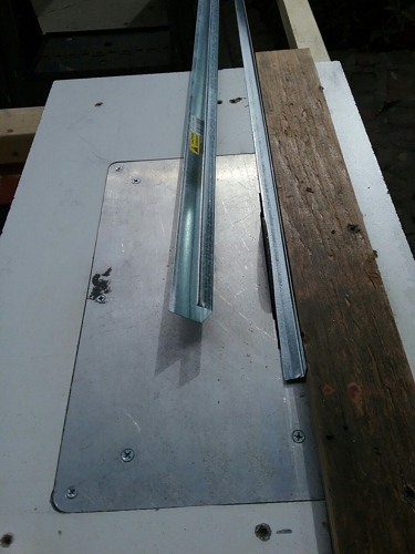
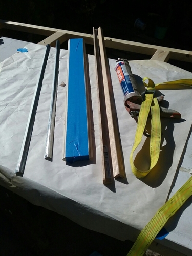
option 2 - I found Plaster Board Edge Bead in a J profile for 15mm or 5/8" plaster board. Bought 3 pieces, each 3 meters long, then cut it 800 mm lengths and trimmed it to 12mm. It is .7mm thick. Bought these at Lowes for less than $4.00 total.
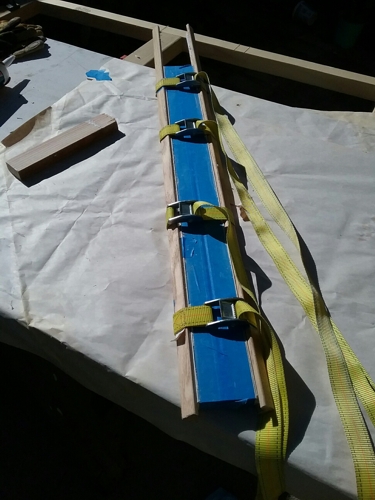
I removed the burrs from the metal and glued them to the wood with construction adhesive.
Suso I will email photos to you for attachment.
Next time I will comment on Tools, materials and the Plans.
Hope this is helpful
Nello
Nello's Build of Router. (with comments on process)
Posted: Wed Dec 30, 2015 8:33 am
by info@paoson
Nello's Build of Router. (with comments on process)
Posted: Thu Dec 31, 2015 3:51 pm
by Panelli
UPDATE:
Tools
I used one day to fine tune my table saw and router table, and made the belt sander table similar to the one on Paoson site.
I mounted an old circular saw with an abrasive cutting disk under a table for trimming the J bead metal.
Materials
J Bead metal as described above was very inexpensive and came out well. Cutting, removing burrs with a file took time.
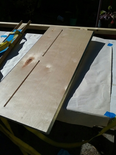
18mm multi ply plywood. 48" x 96" is approx $60. I asked if they have anything with surface damage. Bought a piece of pre-finished birch with scratches on the surface for $17.00. I should have asked about the grade of the material. As I cut it I notice a few voids and repairs in the ply.
I will not use it for the Z parts, I have a few small pieces of Maple ply I will use for it.
Hardware
I have considerable time in working out the hardware.
Using M8 bolts for all the bearing axles.
Using SAE 1/4" -20 and 5/16" -18 bolts every place else. (Greater availability of inserts, knobs etc. and cost less than metric.)
Plans
They are great. I had to use different sheets to get all the information for making parts. It would be easier if the full scale layout sheets had the location and dimension for holes and slots.
Order of work.
Built rails and track for X and Y.
Built the Y axis frame first. It gave me opportunity to test my tools and assemble process. Went great.
Next will start on X frame.
More later.
Nello
Nello's Build of Router. (with comments on process)
Posted: Tue Jan 19, 2016 5:10 pm
by Panelli
UPDATE 2
I really enjoy building this project. Thank you, Suso.
Have completed X and Y. Will not build Z until alignment of X and Y is completed.
ALIGNMENT COMMENTS
A. The Bed (part #1) and the wall (part #19) should must be at perfect right angles to each other over the entire length of the bed (#1).
Problem. My project is off from .5mm to 3mm.
WASHERS. My washers, used for bearing spacing are not a uniform thickness, therefore the bearings ride at different highs on the track. By repositioning washers and enlarging the bearing axle holes in part #9, I was able to get perfect alignment over the full bed with the wall #19 at its middle position, over the entire bed. Happy!
B. The wall (part#19) should be at perfect right angles to the bed (#1) at all up/down positions.
Problem. My project is not.
I will work on this and give another update
Nello
Nello's Build of Router. (with comments on process)
Posted: Wed Jan 20, 2016 8:46 am
by Suso
Thank you very much for your update, I hope everything goes ok!
Nello's Build of Router. (with comments on process)
Posted: Sat Feb 06, 2016 3:47 pm
by Panelli
UPDATE 3
Regarding B. above. My part #19, the wall, was not perpendicular to the bed #1 in all up/down positions. Off up to 3 mm. By re-positioning the guides, part #13 and #14 I attained correct alignment throughout the full up/down positions. However it was difficult to crank the wall up and down because of increased friction.
Modification. To reduce friction and maintain alignment Part # 14 was modified. Rather than being tightly screwed in place, I made an elongated 5 mm hole at 150 mm from the top and bottom of the part. Place a 5 mm bolt thought the holes and left them a little loose.
I then put bolt through the back of part #12 to "push" tension onto part # 14. Works great.
Note: Did this to both parts #14
I have just started the Z axis parts. more later.
Hope these notes are helpful to someone.
Nello
Nello's Build of Router. (with comments on process)
Posted: Mon Feb 08, 2016 8:46 am
by Suso
well done Nello, I hope everything goes ok!
Nello's Build of Router. (with comments on process)
Posted: Fri Feb 19, 2016 3:09 pm
by Panelli
UPDATE 4 Finished Z
I finished Z. The alignment of the plate for the router is not at 90 degrees to the bed, but only off about half a millimeter.
I am planning a modification to the Z router plate.
In the States tools with 43 mm collars are limited and expensive. In order to stay in my goal of "build as cheaply as possible", I am using a low cost trim router with a 63 mm diameter. A drill will a collar is also difficult to find. The drill will require a different mount than the router.
MODIFICATION
I intend to make two different tool mounting plates, one for the router and one for the drill. The plates will mount to the existing Z plate and will with four 8 mm threaded inserts. I will make the new plates from 12 mm hardwood ply, each with the same bolt pattern, thus interchangeable. The added benefit will be that the new plates will allow for some adjustment. They can be shimmed to get it exactly true 90 degrees to the bed.
Do you have any cautions, suggestions or comments on a this modification?
Nello
Nello's Build of Router. (with comments on process)
Posted: Fri Feb 19, 2016 4:10 pm
by Suso
wrote:UPDATE 4 Finished Z
I finished Z. The alignment of the plate for the router is not at 90 degrees to the bed, but only off about half a millimeter.
Don't worry about that, 1mm is not important.
wrote:UPDATE 4 Finished Z
I intend to make two different tool mounting plates, one for the router and one for the drill. The plates will mount to the existing Z plate and will with four 8 mm threaded inserts. I will make the new plates from 12 mm hardwood ply, each with the same bolt pattern, thus interchangeable. The added benefit will be that the new plates will allow for some adjustment. They can be shimmed to get it exactly true 90 degrees to the bed.
Do you have any cautions, suggestions or comments on a this modification?
Nello
That's a good idea, but keep in mind id the router is much more heavy you may need a stronger spring. Anyway take a look to this link, I've found a few places in USA where you can find some routers with the 43mm euroneck
http://paoson.com/en/forum/55s/where-to-find-the-43mm-clamping-collar-router
Nello's Build of Router. (with comments on process)
Posted: Sat Feb 27, 2016 3:53 pm
by Panelli
UPDATE Choice of Router and Drill
Hello Friends
I am using a very inexpensive 1/4" trim router, made in china. It cost $28.00 US. 25,000 rpm, 400 watts. I am running it thought a variable speed controller, $20.00 US. Works fine.
People are using this router on CNC routers with great success in wood. It is has a 63 mm collar and is not heavy.
Drills with the 43 mm collar are not common here. I one with a 13 mm chuck.
Using the separate mounting plates as, described above, is correct solution.
I am wishing I had more time to work on this project.
Nello