I came up with this idea as a way to avoid difficulties and wasting time when preparing a CNC for certain jobs. Unless the project is very repetitive, sometimes you can spend more time preparing the CNC than working on the project itself.
With this manual router, you can drill holes and mill very fast. Its 43mm clamping collar makes it very versatile and switching between milling and drilling takes very little time.
3D Router Plans
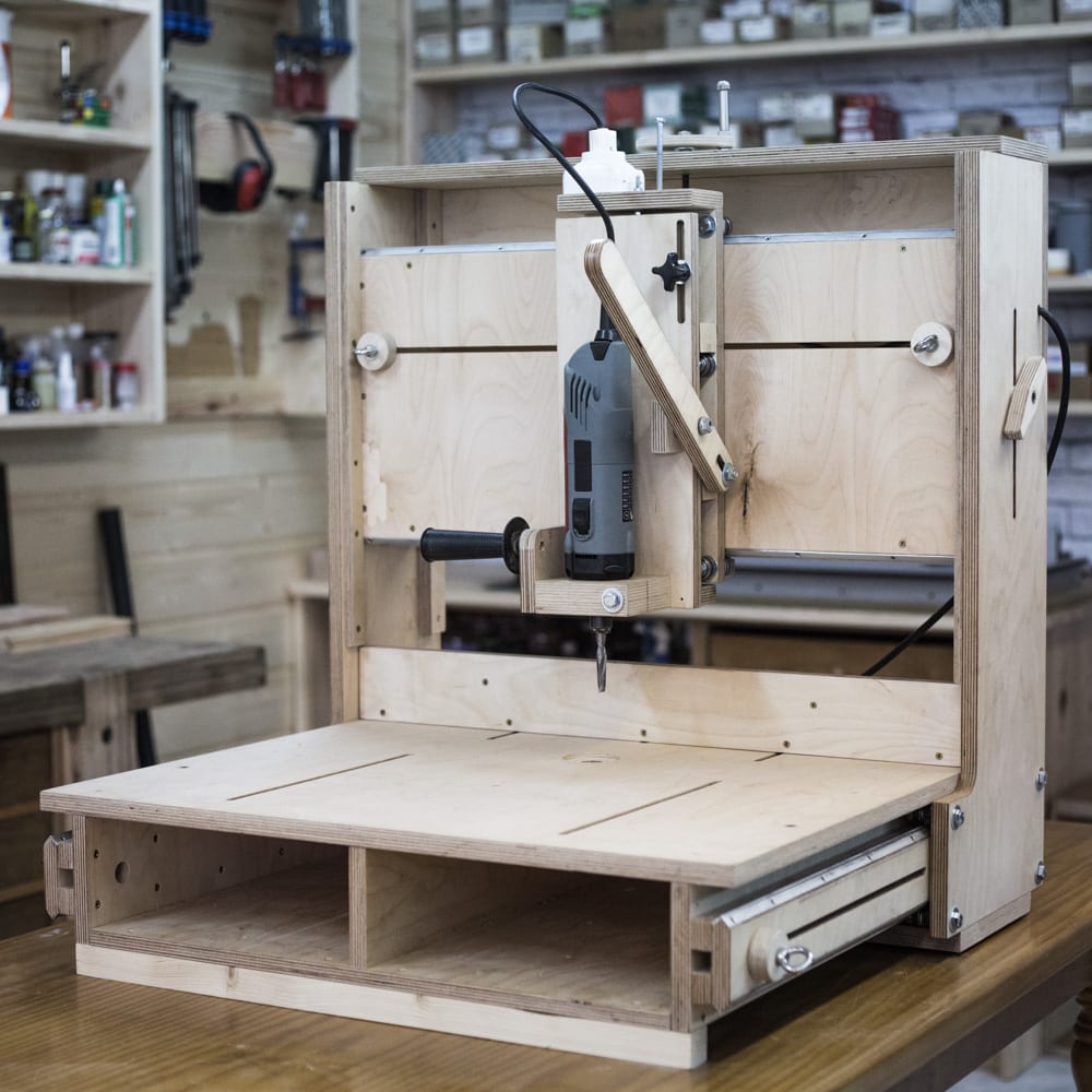

There are definitely lots of wooden router table and CNC router plans on the net. What makes this project stand out is the feature set and the cleverness of how it’s all put together, as well as its design, which aims for maximum versatility.
This router table can be used as a 3-axis drill press, sanding station (by mounting a drill sanding drum on it), and a 2D router. Also, you can make simple shapes 3D using a reference model. Using a series of accessories, you can also cut circles, squares, and copy a 2D reference model.
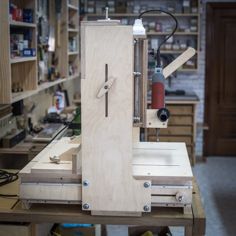

It can also be adapted to any kind of router by modifying the clamping system, as some of my readers have done, although it would lose the ability to quickly swap between cutting and drilling.
This tool has countless uses. As a guitar maker, I intend to design a series of templates for guitar bodies and necks to be made with the 3D Router, without switching on my CNC. Apart from that, it can also be used in other woodworking projects. I have tried to make an easy-to-build design, rather simple and cheap.
Overall measurements: 800mm high, 740mm width and 700mm depth.
Usable measurements: 425mm in X Axis, 535mm in Y axis and 185mm in Z axis.


This is the 3D model of SketchUp included in the plans that you will find on my website. If you are interested in collaborating with my web or building your own 3D Router, here you can download them.
How to make the 3D Router: Ep1
This is the first video in the 3D Router series. I’ll start by cutting all the pieces with my router & saw table to start this project. It takes a great deal of precision, as well as woodworking expertise, to put this tool together. I’ll mark all the pieces according to the plans to cut them later.
The cuts made with the disc and the millings must be perfectly straight and properly aligned, otherwise the machine could vibrate, affecting results.
You could also take the cutting list to a woodworking warehouse. They will cut and reference all the pieces for you, so you will only need to machine the smaller cuts and put the pieces together.
How to make the 3D Router: Ep2
In this second video I’m going to finish cutting, sanding, and preparing all the pieces according to the plans; such as the rebate for the drive spring. This spring must be able to withstand the weight of the Z axis with the router mounted. They are easy to find in agricultural spare part stores. After that, I start assembling the L-shaped pieces of the axes.
These Ls must be made of iron or steel. I’ve used aluminum, but since this metal is softer than the bearings, these carve a groove in the aluminum, which could cause play in the long run. You can glue or screw them in making sure the screws don’t touch the bearings. Use rulers to make sure they’re straight and parallel.
How to make the 3D Router: Ep3
I start this video assembling all the X axis pieces, and right after that, I start installing their bearings, as you can see at 2.45 in the video.
We must make the 8mm hole a little bit bigger in the direction and areas marked in the plans so that we can adjust the position of the bearings to the metal profile without any play. This adjustment system is quite simple, but effective when made correctly.
After that, I attach the plywood Ls acting as a bridge. I’ll use wooden dowels to reinforce some of the parts that require greater resistence. In order to drill these holes straight I’ve made a template that will come in handy at times like this.
I’ll also install the lower part that joins both plywood Ls. Without this piece, the router would sway when applying force when milling, especially when milling on one of the ends.
After that, I screw two strips of pine onto the lower part to create some distance between the machine and the table where it will rest, as well as to allow X axis movement.
How to make the 3D Router: Ep4
I start this video by screwing in the guideway parts supporting Y axis movement. Needless to say, the frame must be perfectly aligned to allow smooth sliding over the plywood Ls, otherwise it could get stuck when adjusting the height.
I finish machining and assembling all the Y axis pieces and, once that’s done, I start machining the Z axis parts. I start by drilling all the necessary holes with the column drill.
At this point, you could say we’re halfway through!
How to make the 3D Router: Ep5
Here you can see how I finish machining and assembling all the Y axis pieces. Then, I start attaching the bearings, which move along the Y axis frame, which, in turn, moves up and down along the X axis L-shaped plywood parts.
I must follow the same steps as with the other bearings, making the hole referenced in the plans bigger so that we can adjust the position of the bearing.
Due to the complexity of axes Y and Z, this might be the part that requires the most patience and skill in the entire project. There are a lot of small, fiddly pieces here…
Screw in the pieces holding the followers. Since these will have to withstand a great deal of force, we must ensure they’re firmly locked in place. I’ll use screws, dowels, and glue.
How to make the 3D Router: Ep6
Now I’ll move on to the Z axis. I’ll finish machining and putting all its parts together. The hole for the 43mm clamping collar must be tight and be made with a bit with the exact measurement, an adjustable bit, or with a CNC.
Make sure the router is firmly attached or it could come off mid-project, which could be dangerous.
After machining the tightening system for the router, I put the clamping collar in place. It has to be tight to avoid vibrations when working.
Now I’ll try putting the spring in place. By tightening and loosening the eye bolt we can adjust the strength of the spring. It’s a simple system that’s turned out to be quite effective. All that’s left is to mount the Z axis.
How to make the 3D Router: Ep7
In this video I’m going to finish the Z axis, the actuating lever as well as other accessories such as the elevator control. The two screws holding the actuating lever must be a little loose to allow rotation. It’s best we use a self-locking nut.
I’ll also make a turning wheel allowing us Y axis vertical movement, as well as all the fast clamping sleeves and the axes’ brakes, also made of leftover bits of 18mm plywood.
After that, I’ll cut and assemble the support with screws and glue the two guiding parts that fit in the worktable to it. These will help us keep it in perfect alignment, making it easier to mount workpieces.
How to make the 3D Router: Ep8
This is the last video in the 3D Router series. First I’ll finish machining the guideway with the 3D Router itself. As you can see in the video, this router will be quite useful for this kind of millings.
Once I’ve checked the guideway slides along its rails smoothly, I prepare some holes for place a few threaded inserts allowing us to lock the guideway in a specific spot.
Once again, with the 3D Router I’ll machine a couple of grooves for the worktable, allowing us to insert some small clamps to hold the workpieces. We could also use t-track guides, but this system is cheap and efficiente.
I’ll also make the 2D and 3D followers. The parts holding these followers must be firmly attached and secured. It’s best we use glue and screws.
Finally, I’ll machine all the necessary parts to use the drill sanding drum on my 3D Router.
Making an electric guitar with the 3D Router: Ep1
Before starting this project, I install a simple lock on the Z axis that makes it possible to mill from the rear without having to activate the lever. This is very useful in some tasks involving the 2D follower and the 3D follower.
I’ve made some templates for the 2D contours and the 3D top of a guitar with a CNC. If you don’t have a CNC, I suggest you have them made by someone who does. They could also be made by hand, but this would require a great deal of precision.
A good set of templates will allow you to repeat projects as many times as you wish!
We could also use a real guitar as a template, but you would have to protect its surface to avoid damaging it with the followers. I’ve made two 700x350x10mm bases on MDF to hold and position the workpieces.
Making an electric guitar with the 3D Router: Ep2
As you might have guessed, in order for the milled piece to be identical to the template, the 2D follower must be of the same diameter as the bit, though alternatively, we could install a smaller bearing if we want the piece to be larger than the template.
By using different bit and bearing sizes, we can use the same templates for different milling jobs.
With a piece of the same material I’ll use for the electronics cover, I adjust the milling height. After turning the template and guitar, I continue machining the front part for the pickups, switches, and neck of the guitar.
The depth of each Z pass depends on the material and tools we use. Ideally, you should proceed smoothly and gently when using your router. As you can see at 2.50, the 2D follower can be used from the front and rear. I personally prefer doing it from the rear because I can focus more on the template.
When I’m about to mill the contour of the guitar, I realise that the 2D follower bumps against it, making it impossible to proceed. This can be easily solved by trimming the follower a bit.
Now here comes the most interesting thing about this machine, which is being able to reproduce the 3D top of any guitar. I adjust the templates and put the follower in place.
Making an electric guitar with the 3D Router: Ep3
I lower the entire Y axis rig, bringing the router closer to the workpiece. Then, I adjust the follower’s height to use the 3D follower. Since I’m going to do several Z passes on the top, the bit will be a bit higher up than the follower at first. In the last pass, they should be at the same height.
Using a roughing end mill will give us optimal results in a shorter time. I’m used to sanding this kind of guitars without deforming the top, but if you’re not an expert you can use a curved bit for the last 2 or 3mm, achieving a smoother top that will barely need any sanding.
As with the 2D follower, I prefer sanding from the rear. I can focus more on the template and it’s less dangerous.
I position the 2D template again to mill the binding. If everything’s correct, swapping templates shouldn’t be a problem. If that’s not the case, you could damage the guitar’s body if the bit goes too deep at any point along the contour of the body.
Finally, I’m going to attach the drum sanding drum and sand the contour of the guitar’s body. It’s quite convenient for these kinds of jobs because it can reach all the sharp bends that a belt sander can’t.
3D Router Bearing Upgrade:
After one year of use, it’s time to perform maintenance on my 3D Router. I’m going to focus on the bearings and the aluminium profiles. As I said back in the day, aluminium wasn’t the wisest choice. Some grooves have appeared because the bearings are made of a harder material.
Note: I’m not planning to update the plans of the 3D Router because, as you can see in the video, hardly any modifications are necessary and both systems are good if made correctly and with the right parts.
You only need to separate the bearings 6mm on axis Y and X, and lower the Z axis part another 6mm as seen in the video.


Superbe travail d’ingéniosité bravo!!
Plz can you help me with the dimensions you used?
Bonjour,
3D Router Table Plans est-il en français aussi
car je trouve les vidéos impeccables merci pour les démos
Большое спасибо что вы так щедро делитесь своими изобретениями. Успехов.
Спасибо за ваши идеи. Браво!!!